EMI Testing Antenna

Log Periodic Antenna: 200M - 18GHz
Tunable Dipole Antenna: 28M - 1GHz
Biconical Antenna: 26M - 3GHz
Loop Antenna: 9K - 30MHz
Horn Antenna: 200M- 40GHz
Omni Directional Antenna: 20M - 40GHz
LISN: 10k - 65MHz
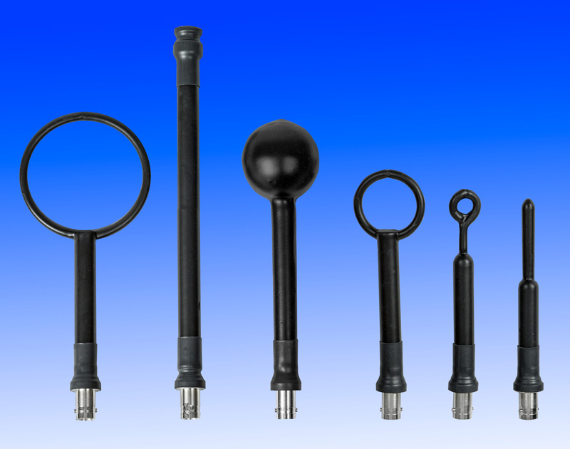
Near Field Probe Set

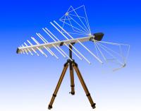
Biconica-log EM-6917C-1
Electrical
Frequency Range: 26 MHz – 1 GHz
Impedance, nominal: 50 Ohms, nominal
VSWR: <2.0:1, typical
Power: 1000 W, peak
Connector: Type N, female
Mechanical
Log Periodic Section:
Length: 1.45 m (57.25”)
Width: 1.02 m (40.2”)
Height: 12.7 cm (5.0”)
55 cm (22”) with antenna mount
Weight: 4.5 kg (10 lb.)
Biconical Elements:
Length: 1.30 m (50.0”) Tip –to-tip
Diameter: 520 mm (20.5”) maximum
The EM-6917C-1, a hybrid combination of the industry standard biconical and log periodic antennas, delivers an unmatched combination of frequency coverage and high power handling capability. Featuring exceptionally broad frequency coverage of 26 MHz to 1 GHz, the EM-6917C-1 eliminates the need for adjustments or switching antennas in most test applications up to 1 GHz, and it does so without compromising power handling capability for transmit applications.
The EM-6917C-1 can be operated as either a transmitting or receiving antenna over its entire frequency range. This may be the only antenna you need to perform many commercial EMI emissions tests, and its integral balun minimizes the effect of cable placement on measurements seen with some other antennas. In additional it’s transmit capability allows generation of the necessary fields for IEC 1000-4-3 (IEC 801.3) radiated immunity testing from 80 MHz to 1 GHz.
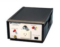
LISN
Electrical
Frequency Range: 10 kHz – 30 MHz
Power Line Frequency: DC to 63 Hz
Current Rating: 15 A Continuous Current 2 Lines
Maximum AC Input:
Line-to-Line: 440 VAC
Line-to-Ground: 220 VAC
Impedance Characteristics: Follows VDE 0876
Specified Curve +-20%
Inductance Characteristics: 50 µH/250 µH
Connectors:
Monitor Port: Type BNC, female
Power Input: IEC320 C20, power cord supplied with customer specified plug
The EM-7823 Line Impedance Stabilization Network (sometimes referred to as a “V Network”) is a two line low pass filter network designed to isolate an electrically operated device from an external power source (usually the power mains). It provides a stable and consistent line impedance at the frequencies where radio interference measurements are made.
The 50 µH / 250 µH network implemented in this LISN may be used in making high frequency conducted measurements according to most commercial test specifications including ANSI and certain FCC, CISPR and VDE tests. It features a current carrying capacity of 15 Amperes.
Power input and output connections are made using standard power mains plugs and sockets. The user may choose from many available styles including European (Schuko), French, U.K., Australian, Japanese and U.S. (NEMA) style connections.
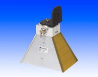
Double Ridged Guide Antenna
Electrical
Frequency Range (calibrated): 1 GHz – 18 GHz
Impedance: 50 Ohms nominal
Average VSWR: <1.5:1
Average Power Gain: 10.7 dB
Average Beamwidth:
E Plane: 53º
H Plane: 48º
Power for 200 V/m @ 10 GHz (typical): 90 W
Output Connector: Type N female
Mechanical
Length: 280 mm (11”)
(includes Tripod Mount)
Width: 244 mm (9.6”)
Height: 157 mm (6.2”)
Weight: 1.8 kg (4 lbs.)
The EM-6961 Double Ridged Guide Antenna is a linearly polarized broadband antenna designed and built specifically for EMI measurements and specification compliance testing.
The versatile EM-6961 is constructed of rugged aluminum, which makes it excellent for use under severe field conditions and the size makes it suitable for use in the limited space of a shielded enclosure.
Applications
The EM-6961 is a linearly polarized antenna capable of operating as either a transmitting or receiving antenna.
Exhibiting highly efficient performance characteristics for a broadband antenna, the EM-6961 is ideal for measurements to meet MIL-STD-461/462 EMI specifications. It is also well suited for radiated susceptibility testing in the microwave range and general transmitting and receiving applications. Antenna factor chart supplied with each antenna.
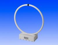
Loop Antenna
EM-6871: 30Hz ~ 1MHz
EM-6872: 10K ~ 30MHz
EM-6874: 20Hz ~ 30MHz
EM-6876: 9K ~ 30MHz
EM-6878: 9K ~ 30MHz
EM-6879: 10K ~ 30MHz
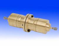
薄膜隔離度測試
Electrical
Frequency Range: 30 MHz-1.5 GHz
Connector: Type N
Mechanical
Length: 40.5 cm (16”)
Diameter: 13.5 cm (5.3”)
Weight: 12 kg (26.5 lbs.)
The EM-2107A is a standard test fixture for evaluation of the electromagnetic shielding effectiveness of planar material. The fixture is an enlarged section of coaxial transmission line and complies fully with the requirements of ASTM test method D4935-1. The measured data relates to the shielding effectiveness due to a plane wave (far field EM wave) from which near field values for magnetic and electric fields may be inferred. The EM-2107A is provided with a reference standard test specimen, a dynamic range specimen. Dynamic range of greater than 80dB is achievable, although the cables and other test system components usually establishes the limiting factors.